Product : Daitron Low Noise Power Supply – No. 1
DESIGN AND CONSTRUCTION OF MULTICHANNEL HVPS FOR PHOTOMULTIPLIER TUBES AT LRC
In the present time a consecutive phaseout from generally usable, modular, analog standard NIMelectronics to compact single purpose devices utilizing digital signal processing hardware takes place. As example one of the main supliers of nuclear measurement electronics, Mirion Technologies (Canberra) GmbH stopped completely the production and selling of NIM-electronic modules in April 2018. Therefore, the replacement of such modules with alternative devices must be performed at LRC in the near future as the currently used NIM modules reach their end of life.
In the course of the setup of different measurement systems at LRC utilizing photomultiplier tubes (PMT), design and realization of a standalone high voltage power supply (HVPS) was started. PMTs represent well-established and versatile tool to amplify the light output of solid or liquid scintillation radiation detectors.
The main focus was given to the following requirements:
・≥2000 V output voltage with positive polarity
・High currents (few mA) for supplying PMTs
・Low electronical noise of the output voltage
・3-4 independent HV channels per device
Although there are appropriate devices available on the market, development of own design was pursued due to their high price point.
Fig. 1: Schematics of the circuit integrating the Hamamatsu C9619 HV module.
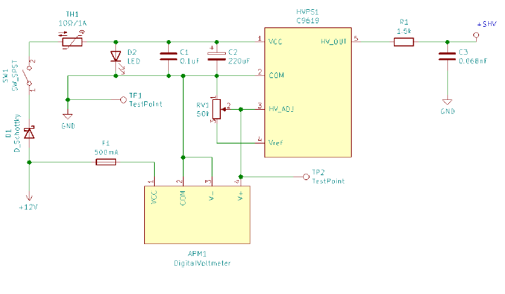
Fig. 1 shows the schematics of the circuit for single HV channel. The needed 12 V DC power is generated by Daitron LFS series low-ripple noise switching power source from the 230 V AC mains. The HV voltage is generated by the Hamamatsu C9619 series module, with maximum rating of +2000 V and 2 mA. Following the manufacturers recommendation, the 12 V power input is HF-decoupled by a large electrolytic capacitor and small ceramic capacitors (C1 and C2). The ripple noise of the output is additionally reduced with a foil capacitor (C3) on the load side of the HV module. A schottky-type diode D1 is used as rectifier on the 12 V input and an NTC-thermistor TH1 protects the circuit against high inrush currents.
A LED (D2) signalizes the power status of the HV module. The output voltage of C9619 is regulated by adjusting the control voltage on pin 3 of the module using a precision 10-turn potentiometer (RV1) connected to the module’s 5.2 V reference voltage source. The control voltage is monitored by a programmable volt-meter and converted to the output voltage by the stored calibration. Alternatively, the control voltage can be read by a multimeter on corresponding test points. A thermofuse F1 protects the voltmeter.
The PCB design was developed with emphasis on simple assembly and maintenance as well as modularity. The control and display elements (switch, LED, potentiometer, voltmeter and the control voltage testpoints) are connected to the PCB using molex-type connectors. The board was designed using the KiCAD EDA software, produced in small series by a professional PCB manufacturer and assembled at LRC.
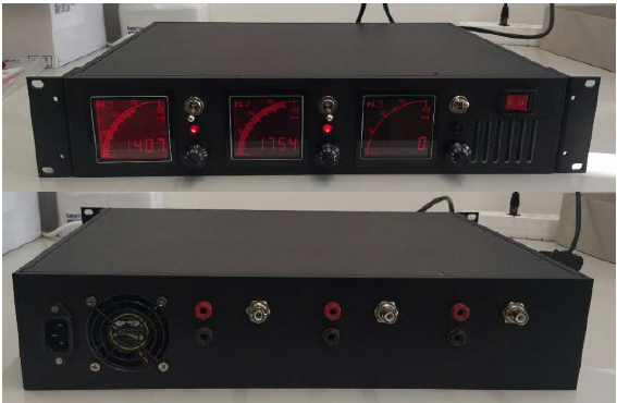
Fig. 2: Front panel (top) and rear panel (bottom) of the HVPS unit integrating 3 HV channels in 19” chassis.
A chassis was designed and manufactured using CNC machining at PSI. With the current design, 3 HV modules with all necessary controls and one 12 V
power supply fit in a single 2U 19” rack mountable enclosure (s. Fig. 2). The controls of the power modules are on the front panel. The back panel contains SHV-type plugs for the high voltage output and 4 mm banana jacks to easy monitor the control voltage with external voltmeter. Low-RPM 60 mm fan on the rear prevents overheating.
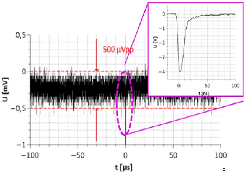
Fig. 3: Baseline of a PMT signal using the designed HVPS with a Hamamatsu R331 PMT and E5859 base. Only very low random noise in the order of 500 μVpp is observed. In comparison, the magnitude of real signals is few volts (see inset).
Initial tests verified the correct electrical functionality of individual boards and of the assembled multi-board setup. The ripple noise of HV output cannot be measured directly with equipment available at LRC. Nevertheless, investigating signals from a PMT connected to the designed HVPS-board with an oscilloscope shows random baseline oscillations on the very low level of 500 μVpp (see Fig. 3) and no visible harmonic frequencies over the whole frequency range.
※This is CITATION from Paul Sherrer Instutue : PSI _LRC _AnnualReport 2018 . Page 27 : https://www.psi.ch/en/lrc/annual-reports
DESIGN AND CONSTRUCTION OF MULTICHANNEL HVPS FOR PHOTOMULTIPLIER TUBES AT LRC (J. Ulrich, R. Dressler, D. Herrmann (PSI))